The jet engine
There are two types of jet engines:
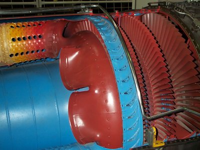
Axial, in which the air flows strait through the engine, like the J-79 below.
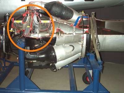
Centrifugal, in which the air is thrown aside, like the Rolls Royce Nene, at the bottom of this page.
The drawing at the other page is not very clear:
Let's have a closer look at the three main parts of a jet engine.
The Axial jet engine
Let's start with the compressor.
In photos 1 - 7 the axial General
Electric J79 is shown; this is for instance the engine of the Lockheed F-104
Starfighter. It is built in the fifties, but works the same as the modern jet
engines. This engine is a turbojet. On the previous page you've learned that in
this type of engine all air passes the engine.
The drawing above shows a hollow shaft with compressor blades, the little "wings".
The shaft becomes thicker to the right and the wings become shorter. The shaft
with all the blades turns around very fast. In the case of the J79 7500 rpm. What
is not clear in this drawing, are the blades attached to the casing, the outside.
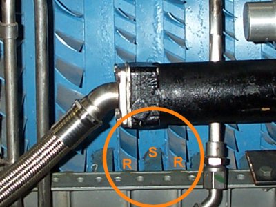
Photo 3 shows
how it really is done. The blades R are mounted on the hollow shaft, the rotor.
This rotor is the rotating part. Blades are also attached to the casing, which
is the outside of the engine. This is called stator. In the picture it is
labelled S. The rotor blades are running very close to the casing, to
prevent air escaping along the blades. But touching the casing is prohibited!
So there are rotor blades that turn and stator blades
that are motionless attached to the casing:
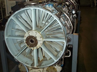
Photo 1 shows the rotor blades and stator
blades in front of the jet engine. They are the first to suck in the air.
Photos 2 and 4 show the rotor shaft
becoming thicker and thicker, while the length of the blades decreases.
What makes photo 2 a little complicated is the mechanism to move the stator
blades of the low pressure compressor a little. Many engines have those variable
stator vanes. They prevent stalling the engine (loud bangs, flames....).
In high pressure compressors they are less common.
 |
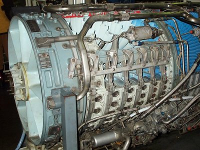 |
| 1 front of the compressor | 2 The
"low pressure" compressor with variable stator vanes; the piston moves a rod, which in turn moves the rings. The rings move the variable vanes by means of bell cranks. |
In what way do turbine blades
compress air?
Well, look at photo 3. The rotor blades R scoop the air and give it a
great speed. Stator blades S, are in a different position and changed the speed
into pressure. It is one of the laws of Mr. Bernouilly: the system acts as a
venturi, in which a divergent opening changes speed to pressure.
After passing one set of blades (rotor and stator) the pressure is a little
higher. Raising pressure causes heat, like the bicycle pump. After passing each
set of vanes the air is aproximately 20 degrees centigrade warmer...
The next set of blades is shorter again, because of the higher pressure.
In this way the pressure is built up step by step by the low- and highpressure
compressor. The air is zig-zagging through the engine.
Eventually the pressure at the end of the compressor can reach 40 bar (580 psi) like in the Rolls Royce Trent 900. That pressure is 20 times the pressure of a car tyre.
The compressor can provide ample air for the combustion chamber, so a part can be tapped. This is called bleed air. This bleed air can reach well over 300 degrees centigrade. It is used for ice protection in the leading edges of the wings and the cowlings of the engines.
If bleed air is cooled by the cold air high up in the atmosphere and treated by an airco as well, it can be used to pressurize the cabin very well. That is why you sometimes can smell the exhaust gasses when the thrust reversers on the engines are applied, in order to have extra brake capability.
 |
 |
| 3 R = Rotor blade S = Stator blade Back | 4 Long
rotor blades at the left, short ones at the right (in the direction of the combustion chamber. |
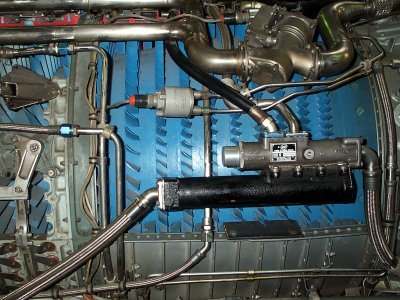
The combustion chamber
The compressor is followed by the combustion chamber (photo 5). In the pictures below you can see it consists of a number of cans, interconnected by tubes. Nowadays this usually is an annular combustion chamber. Left the fuel is sprayed into the can (in fact it it atomized). Photo 6 shows it in detail. The cans, or more accurate the tubes, are perforated, so compressed air can cool the material. Air entering the tube from aside cools the gasses and lower the airspeed, to prevent the flame blowing out. At the engine start a spark plug is used to ignite the fuel/air mixture, but if the engine is running the flames sustain. Only when flying in rain of snow, the pilot turns on the ignition to prevent a flame-out.
 |
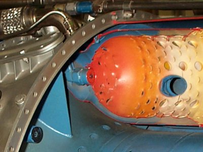 |
| 5 the combustion chamber | 6 the atomizer of the kerosene |
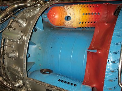
The turbine
Hot gasses enter the turbine. And
there too, you will find combinations of rotor blades and stator blades,
now are called turbine blades and nozzle guide vanes. Here, it
works the other way around, compared to the compressor because pressure
decreases. The rear turbine blades are longer than the ones in front, because
the pressure decreases.
The turbine turns the shaft, so the compressor can suck in air. Sometimes too
much air is pumped by the compressor. As pressure rises at the end of the
compressor and without escape, the air can be blown to the front. This can
damage the compressor very badly and when debris is blowing to the rear of the
engine, other parts can be damaged as well. That is why variable stator vanes
were invented (photo 2), to regulate the yield of the compressor. Other engines,
like the Rolls Royce Avon have valves to let the excess air escape with a
very loud hissing.
 |
|
| 7 the turbine |
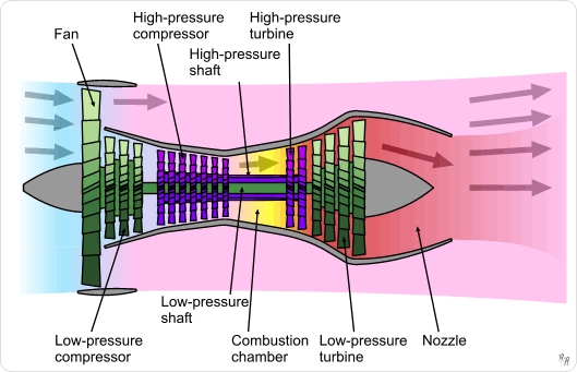
Many jet engines, or gasturbines,
have a different high and low pressure part. This overcomes partly the use of variable stator vanes and bleed
valves to get rid of the excess air because every turbine-compressor pair runs
at an own ideal speed. Above two high pressure stages (purple) drive the high
pressure compressor and the four low pressure turbine stages (green) drive the
low pressure compressor and the fan.
In English this is called a two-spool engine.
The shafts run around each other. Rolls Royce uses three of those combinations
in their big engines: a three-spool engine. They added an intermediate
compressor/intermediate turbine.
This is built between the low pressure and the high pressure pairs.
At engine start the high pressure combination is started. It this delivers
enough hot gasses, the intermediate and low pressure pairs begin to run.
When the low pressure compressor and fan come to speed, you can hear a very low
sound.
The Centrifugale jet engine
This is the oldest type of compressor. It is used in the first jet engines, but still today in small engines up to 1000 horsepower. Below you can see the Rolls Royce Nene:
 |
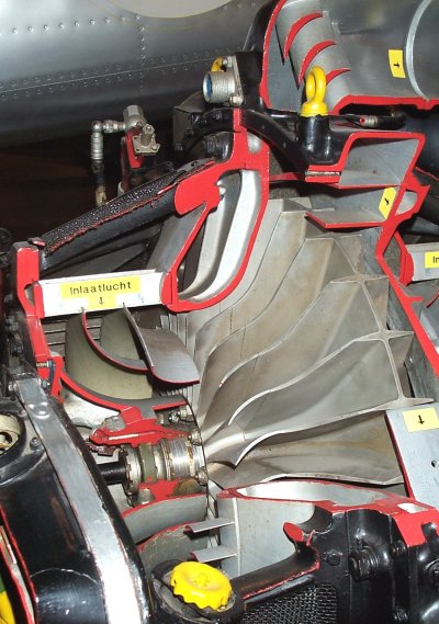 |
| 8 double centrifugal compressor of the Rolls Royce Nene | 9 the centrifugal compressor; air enters in the centre |
Photo 8 shows the complete engine. The small length of the engine is striking. It is shorter than the axial engine, but it's frontal aerea is much larger. The centrifugal engine is often used in small helicopters and as an Auxiliary Power Unit (APU) in the rear of a modern airliner. These APU's provide fresh air and electricity while on the ground. They are also used for starting. In that case they provide compressed air of about 10 bar to the air starters.
Photo 9 shows an enlargement of the centrifugal compressor. Air enters the disc in the center, where the blades are bigger. This air is flung to the outside with force. Special bend plates convert the speed of the air in pressure. Combustion chamber and turbines can be compared to the axial jet engine.
Hans Walrecht
animation found on Wikipedia
photos General Electric J79: Technik Museum Sinsheim (Germany)
photos Rolls Royce Nene: Militair Luchtvaart Museum (Soesterberg, Netherlands)
Youtube:
Rolls Royce Trent 1000 for
the Boeing 787: http://www.youtube.com/watch?v=_AvzoXPEXxk
Flying testbed for the Trent 1000: http://www.youtube.com/watch?v=877vfTgYuPw